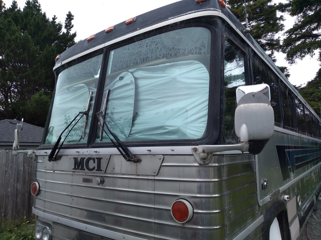
Figure 1: Front of Coach - 1982 MCI 40 ft. Note Hubbell inlet receptacle just below and to right of mirror.
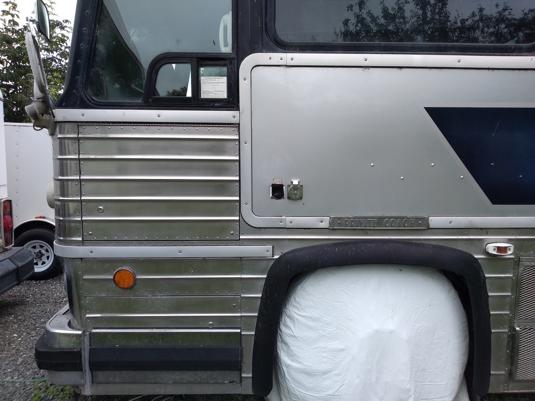
Figure 2: Front Driver Side of Coach. Left Hubbell inlet receptacle has been removed
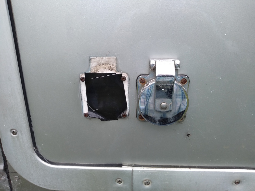
Figure 3: Close up of former 250V 50A Hubbell inlet receptacle location, the Hubbell power receptacle has been removed and hole temporarily covered with duct tape, however it looked nearly identical to the TV inlet to right.
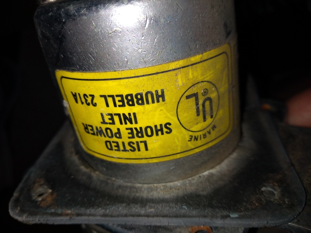
Figure 4: Hubbell inlet receptacle, side view.
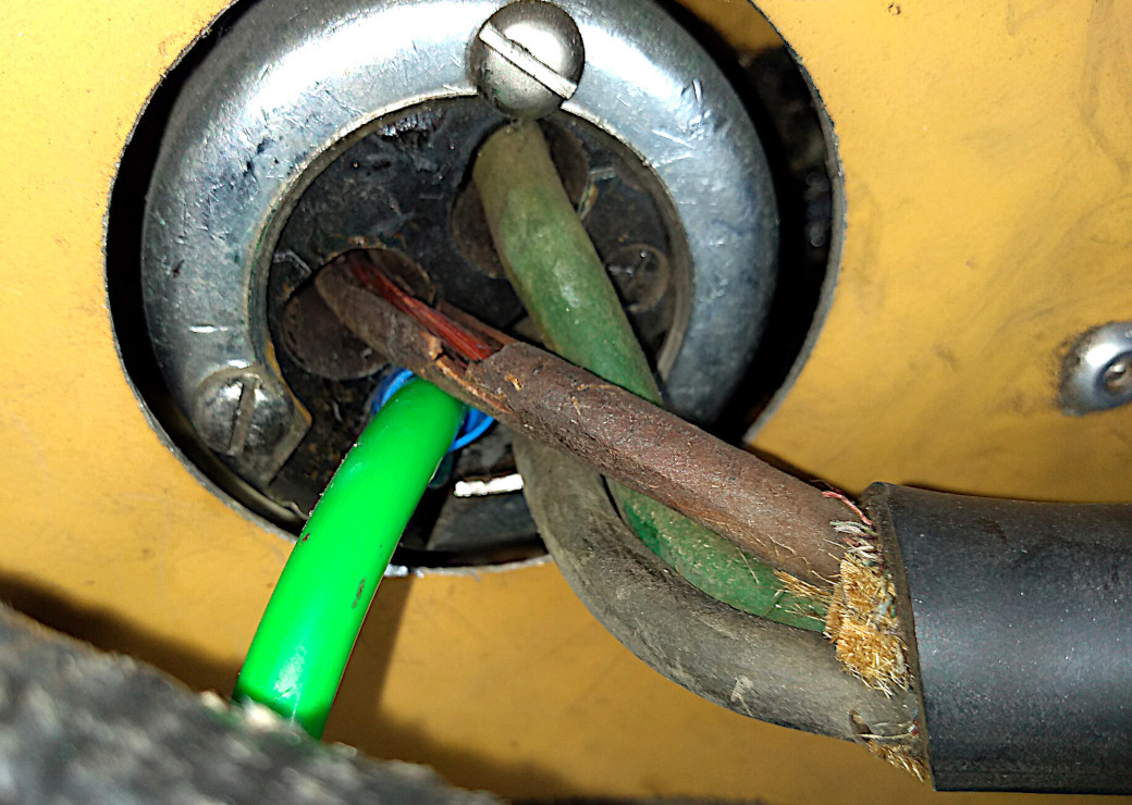
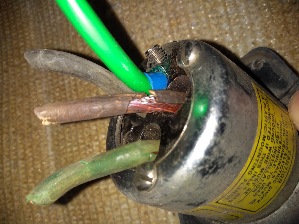
Figure 5: Interior side of Hubbell inlet receptacle. Note missing insulation on 1 of 2 LINE voltage cables (formerly white, should have been red). The dull green was originally the shared NEUTRAL (NEUT) and GROUND (GND) cable. The bright green cable is an upgrade to separate NEUT and GND circuits between inlet and power panel GND bus terminal and NEUT terminals. It will be replaced by use of a 6/4 conductor cable.
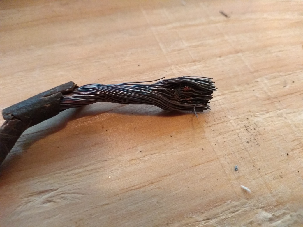
Figure 7: The formerly white LINE level cable with heat or corrosion damage. Screw terminal also damaged a couple of strands of wire.
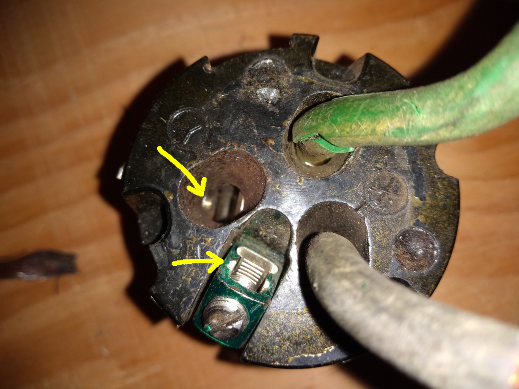
Figure 8: Hubbell inlet receptacle interior GND and LINE terminals do not appear corroded (see arrows).
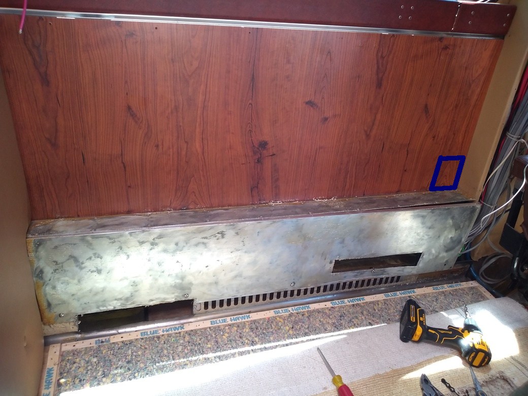
Figure 9: Interior side of the wall on which Hubbell inlet is mounted. The original two piece aluminum cable enclosure is in position. The Hubbell inlet (not visible) is located inside the right end of the vertical panel (at drill end). Blue square right center marks proposed ELCI location.
At least the vertical panel needs to be removable to check the Hubbell interior terminals. This enclosure was covered with carpet held in place with contact cement, which left some carpet strands on top. Another carpet attachment method will be devised (velcro or decorative screws with washers?)
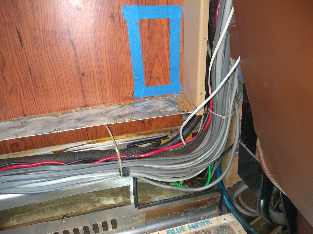
Figure 10: Wider view of Hubbell the same inlet wall and cables with the vertical panel of enclosure removed and a blue masking tape rectangle marking the proposed location of a planned new ELCI enclosure (above center right).
The horizontal rail is the attachment for the top horizontal panel of a long aluminum cable enclosure which runs the full length of the wall rail (panels not shown here, see Fig 13b).Stainless steel HVAC duct perforated vertical panel is the attachment point for the side vertical wall of the aluminum enclosure box (not shown).
The aluminum cable enclosure simply extends the HVAC channel vertically and squares off the top. It was and will be covered in carpet.
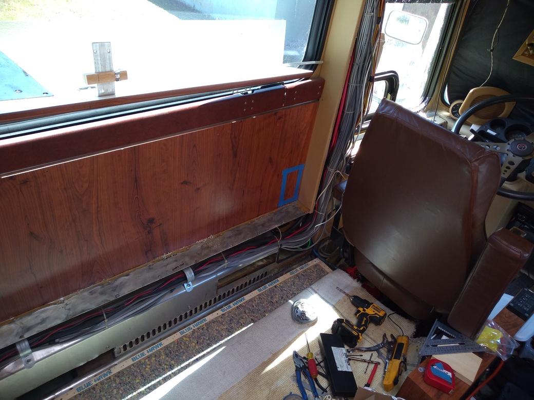
Note the vertical cable channel to the left of the driver's seat.
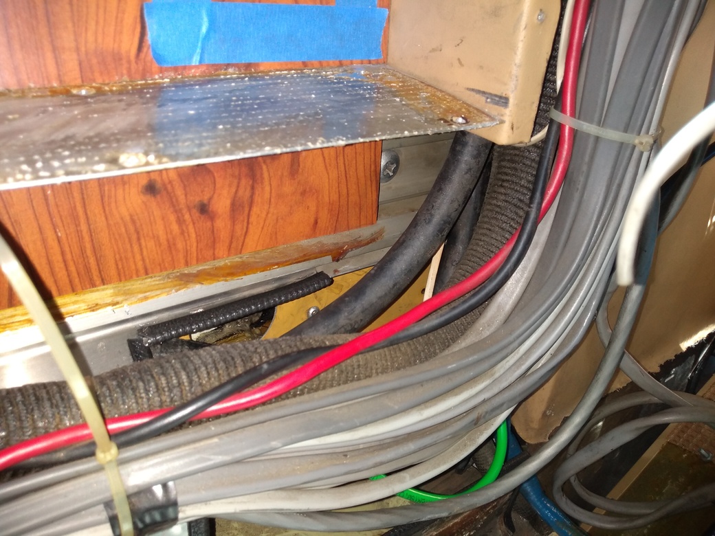
Figure 11: Closer view of the proposed ELCI enclosure location (blue masking tape square). Supply and Load cables will need to enter and exit thru the top of the horizontal metal enclosure, but the horizontal surface (top) of the enclosure can be designed to remain in place during servicing the Hubbell interior.
Figure 12: Even closer view of the area between Hubbell interior and lower proposed ELCI mounting location. Some kind of cable protector connectors will be needed to allow feeder cables to penetrate this top panel. Type will depend on the specific cables and orientation and dimensions of knockouts on the proposed new ELCI enclosure.
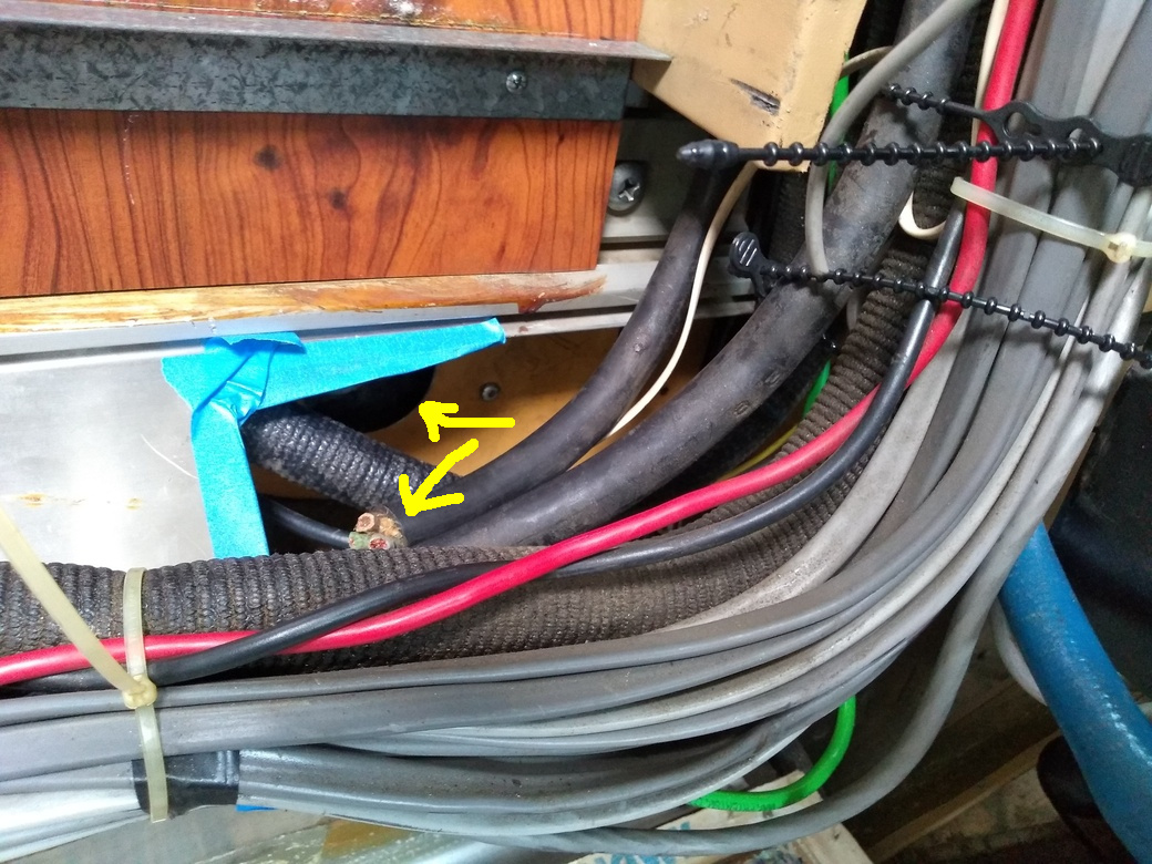
Figure 13: Hubbell inlet receptacle (not shown) barely extends into the circular hole (see top arrow) inside HVAC ducting and below horizontal blue masking tape. Both top and side panels of enclosure have been removed.
Note cut off end of the original 6/3 feeder cable (see bottom arrow) of unknown type (some say SOOW). Existing cable needs to be replaced with 6/4 cable of sufficient insulation, protection, and flexibility to be routed to power panel and switch above driver's side windshield.
Recommendations for feeder cable type welcome.
Note that the cable bundle seen here has been displaced towards camera to provide acccess. Beaded black ties in upper right are temporary only.
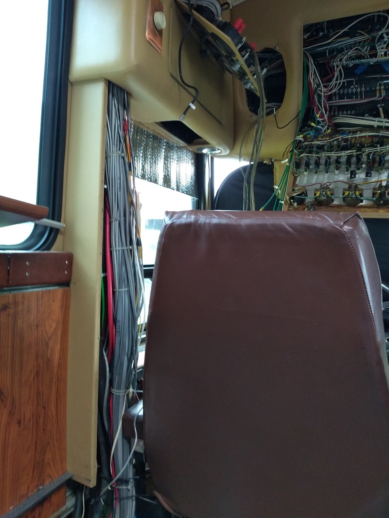
Figure 14: Feeder cable path up thru vertical column to left of driver and compartment above and left of driver's head to front power panel.
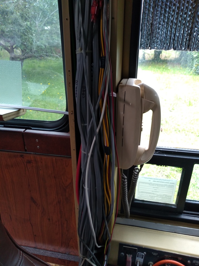
Figure 15: Another view of feeder cable path thru vertical column from driver's seat position. Feeder cable runs behind visible cable bundle.
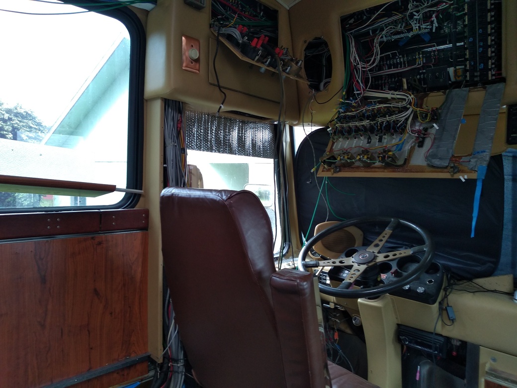
Figure 16: Feeder Cable path, wide view including upper compartments and power panel.
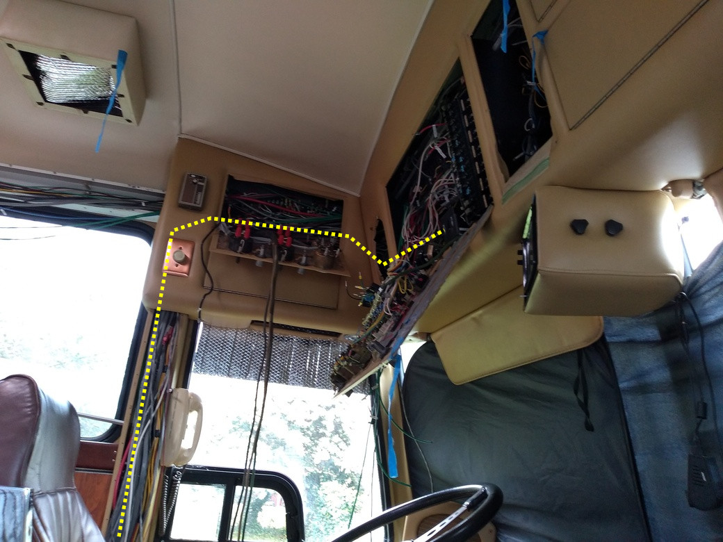
Figure 17: Wider view of driver's area and power panel cabinets, with current and planned path of new feeder cable (dotted line)
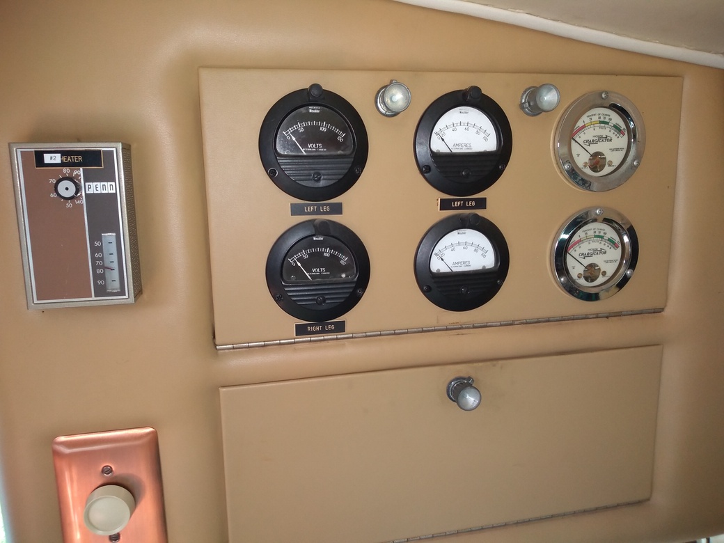
Figure 18: Electrical cabinet above and left of driver's head. Feeder cable must pass behind these gauges.
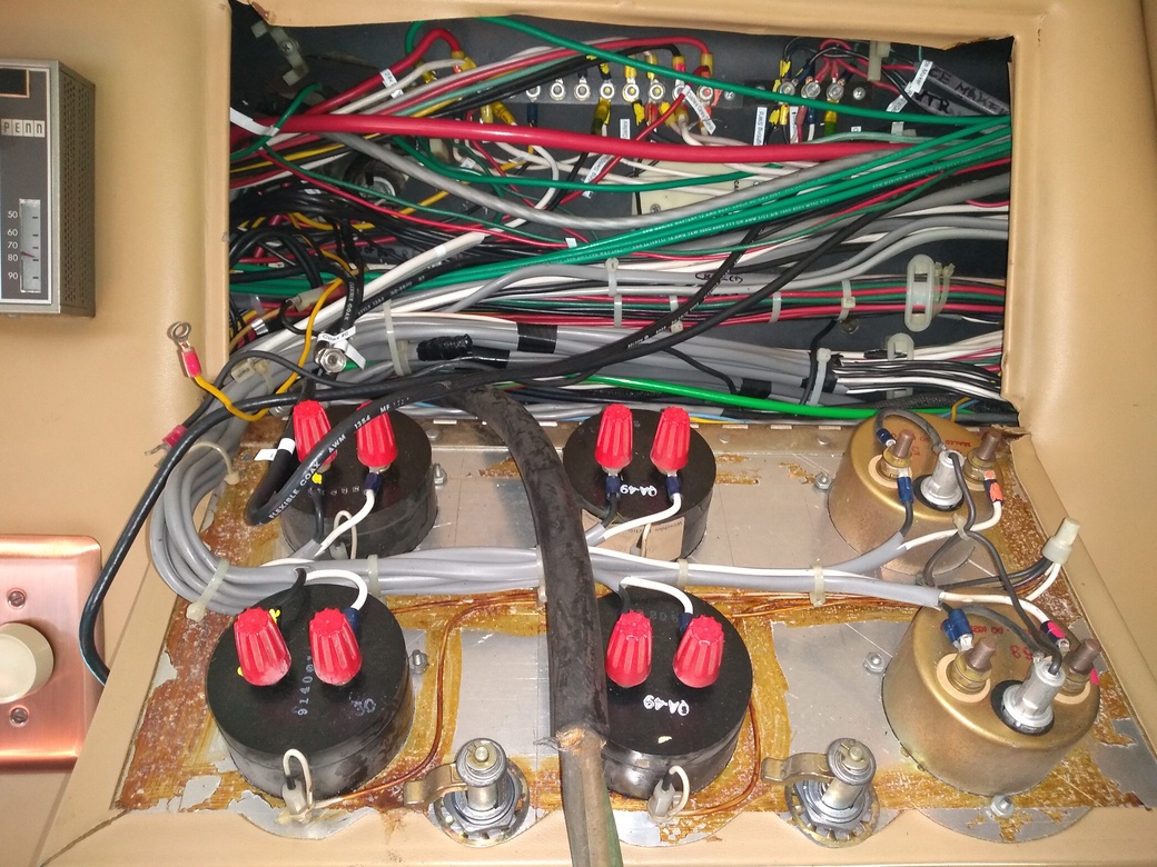
Figure 19: Open door of electrical cabinet (same cabinet as Fig. 17) above and left of driver's head. Feeder cable must pass behind the bundled wires.
Note large black original feeder cable shown partially removed and dangling out and down center of lower half of image.
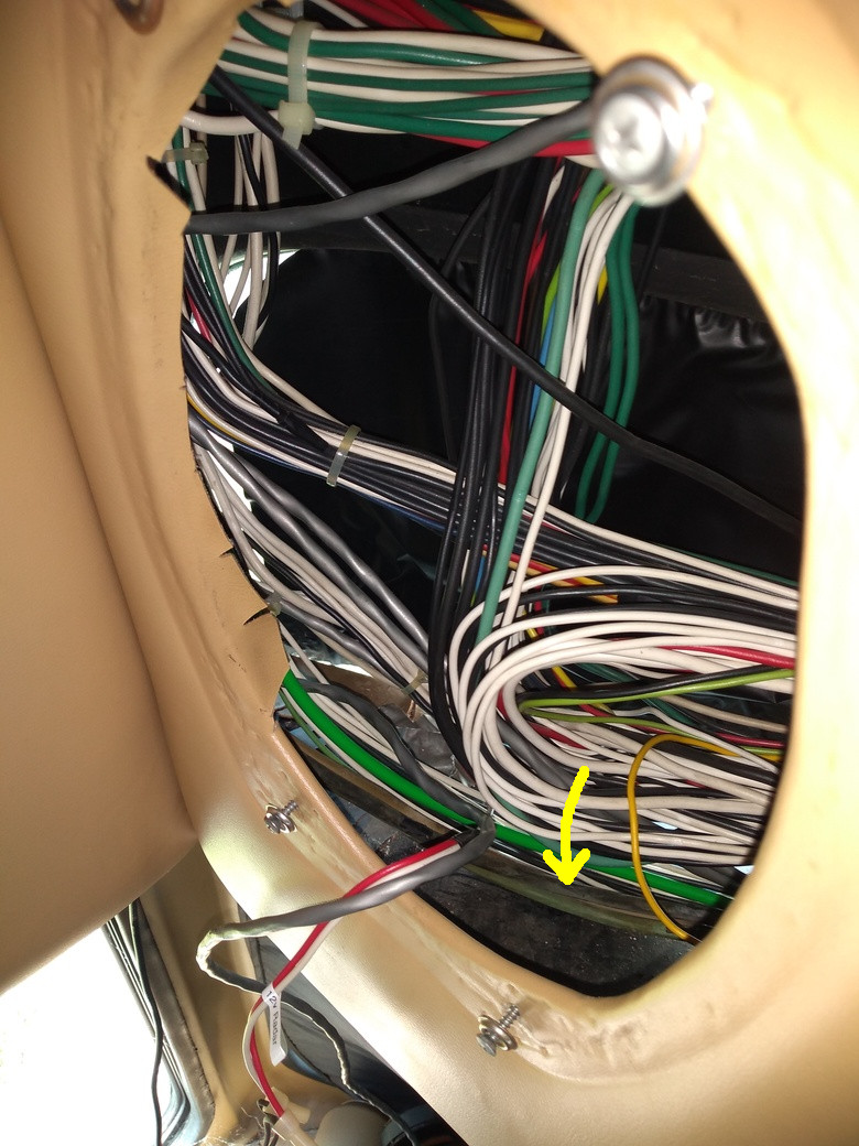
Figure 20: Speaker cabinet thru which feeder cable must also pass is just to the left of the main power panel .
Note existing dark colored generator feeder cables (see arrow) running next to bright green GND cable and former location of original shore power feeder cable.
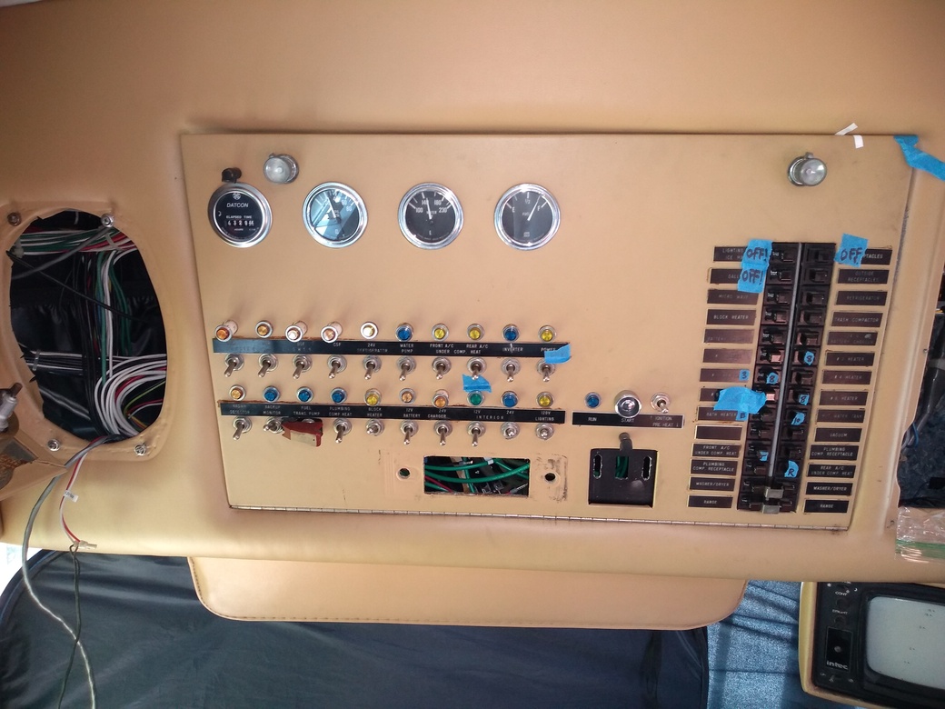
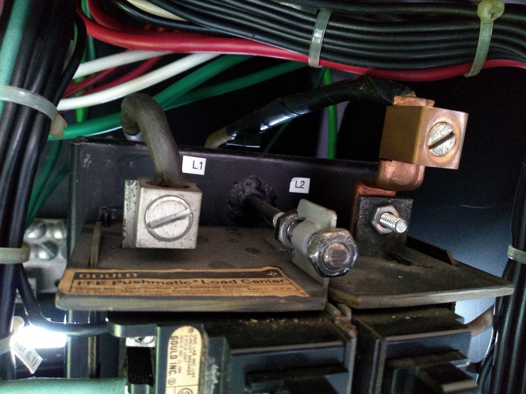
Figure 21: The Main Power panel with its door closed. Note Pushmatic circuit breaker panel on right. Ignore masking tape (used in circuit tracing) and permanently removed radio cutout (revealing green wires). The black square with 3 vertical cutouts just to left of circuit breakers is the location of the main power selector switch (Generator/Off/Shore) which has been temporarily removed.
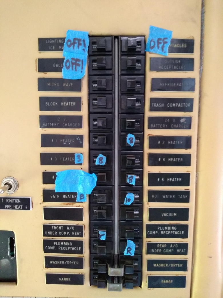
Figure 22: Closer view of the Pushmatic circuit breaker panel. Ignore masking tape used in circuit tracing and heater circuit resistance measurements.
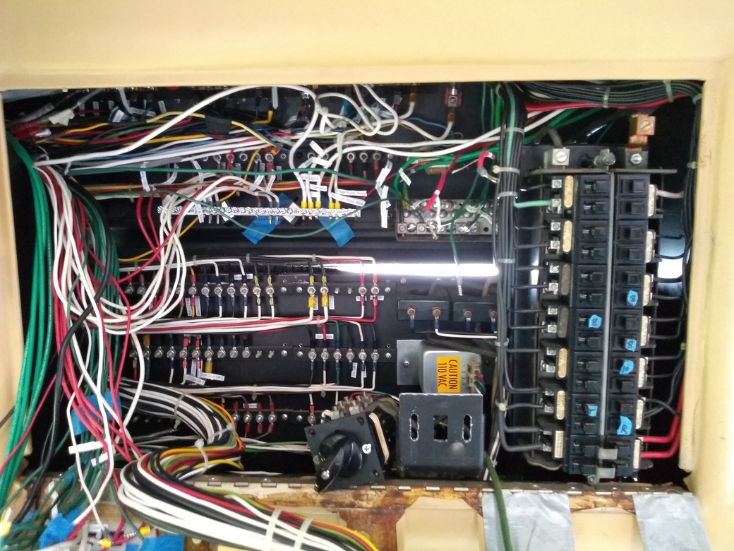
Figure 23: Power Panel with door opened and main power switch dismounted temporarily.
Note the former shared GND/NEUT terminal bus bar to which all green (GND) wires will eventually be terminated and near the top left of the circuit breakers
NEUT wires (most white and red wires) will be terminated to the new NEUT bus bar in upper left of this photo. The result is separate NEUT and GND bus bars.
It would be nice if both were larger to minimize need to insert multiple wires per terminal set screw.
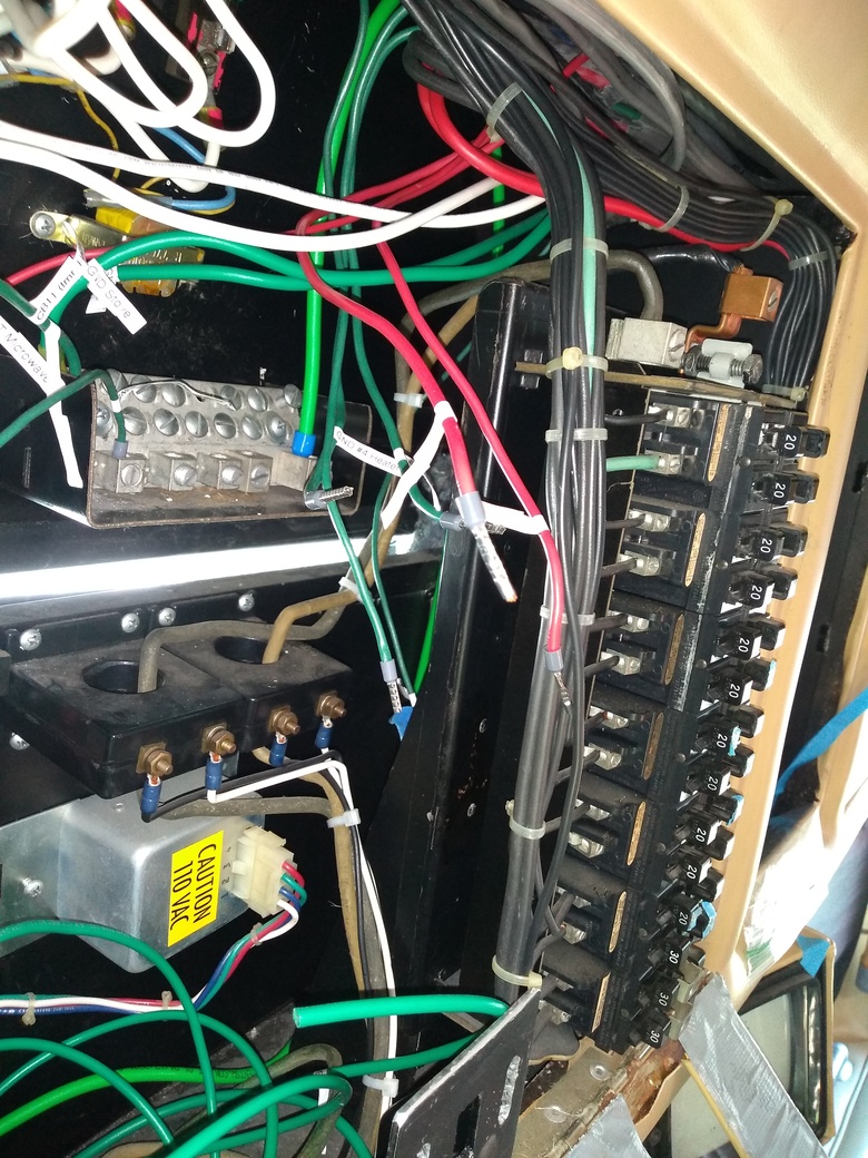
Figure 24: Circuit breaker panel from left side angle. In top left of photo is the former shared NEUT/GND terminal bus which will now be only GND.
Circuit Breaker panel has no obvious NEUT or GND except its vertical black support which appears to be welded to chassis(?).
In center left are seen the black ammeter coils surrounding the L1 and L2 LINE inputs for the circuit breaker panel.
I'm not sure what the Yellow "Caution 110VAC" device is or to what it connects. Oddly labeled because everything except the GND bus bar and NEUT wires are 110v in this area.
Figure 25: LINE inputs at top of Pushmatic circuit breaker panel (Line L1 & L2 120v legs of 240v service). Note possibly modified L2 (extended terminal?).
Recommendations welcome
There is no NEUT terminal except the new NEUT terminal bus bar I have added to separate NEUT and GND (see fig. 22).
Bolt at center of photo is somehow bonded to GND (+/-6 ohm resistance measured) presumably by circuit breaker supported by steel coach chassis. Is this acceptable?
Note that RV code requires that there only be a single NEUT/GND bond and that this NEUT-GND bond must be at the shore connection post or before, not in the RV.
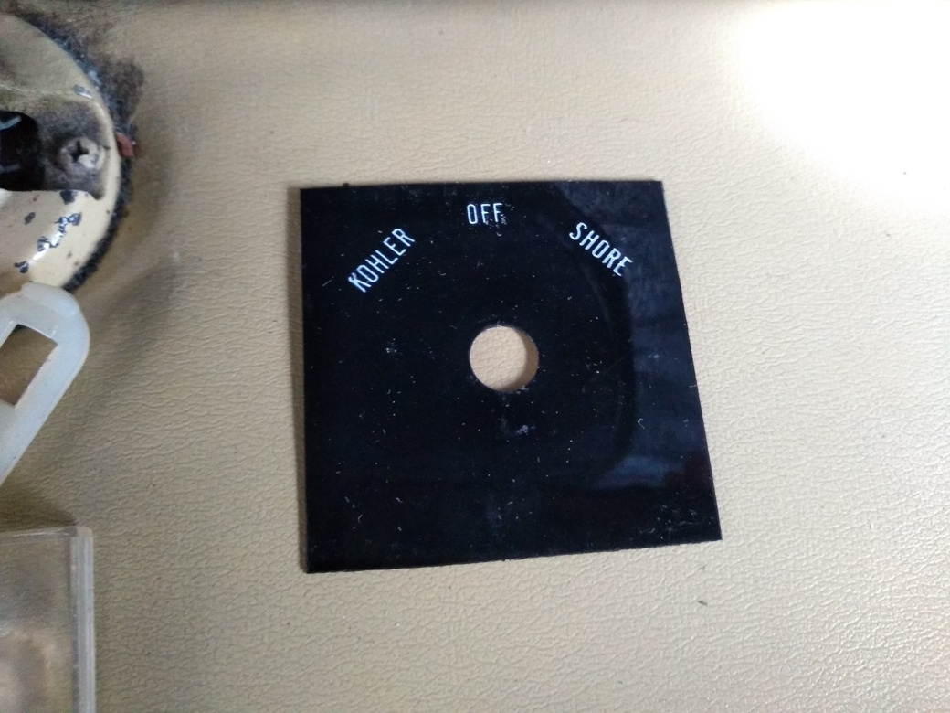
Figure 26: Main power selector switch label (temporarily removed) showing Kohler(generator)/Off/Shore positions
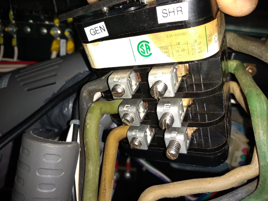
Figure 27: Top (output side) of Main Power Selector Switch in Power Panel. Smaller wires on left are to analog voltage gauges.
Larger White and Black conductors on right supply the circuit breaker panel L1 and L2 inputs. These should be replaced by 6AWG (or better) new White and RED conductors to L1 and L2 inputs for the circuit breaker panel. Recommendations for conductor cable type welcome
The large Green conductor on right formerly served as shared NEUT and GND conductor to the formerly shared GND/NEUT bus bar but will be replaced by a new White conductor to the new isolated NEUT terminal bus bar (see wiring schematic PDF)
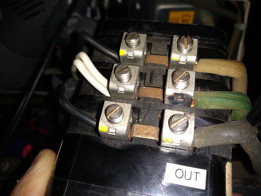
Figure 28: Underside of the main power selector switch. Generator input on left, Shore power feeder cable line input on right, the three feeder cable conductors already removed in this photo in preparation for replacing with three conductors (L1, L2, and NEUT) from a new 6/4 cable. The GND conductor will go directly to the GND terminal bus bar (see schematic)
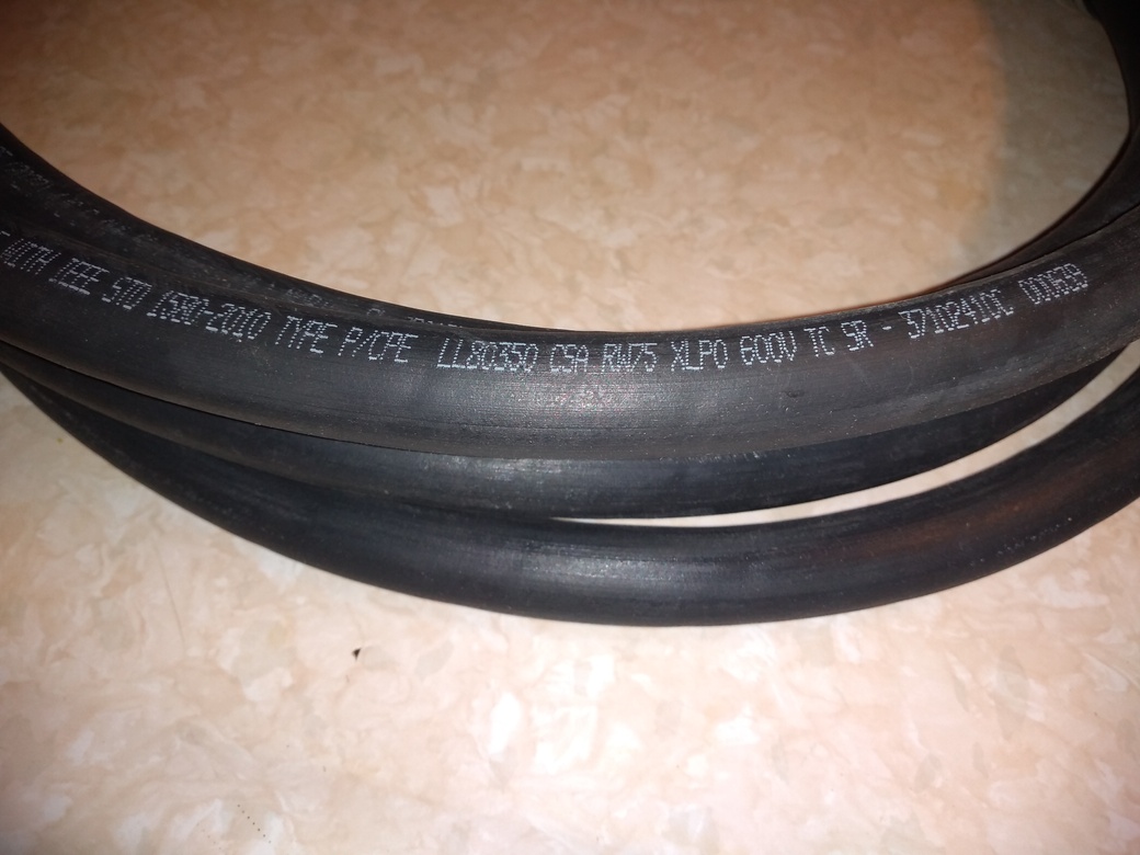
Figure 29: Proposed Type P 6/4 37102410C Amercable markings. Full cable label says: AMERCABLE GEXOL-125 (2022) 4/C 6AWG 600/1000V (UL) MARINE SHIPBOARD CABLE 110C E111461 SPEC 245/1309 FX110CPE-26-600/1000V FT-4 OMD ALSO CLASSIFIED IN ACCORDANCE WITH IEEE STD 1580-2010 TYPE P/CPE LL80350 CSA RW75 XLPO 600V TC SR - 37102410C 000639
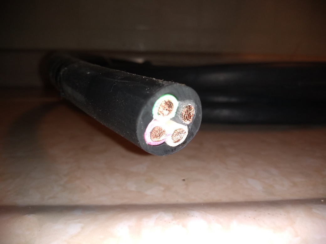
Figure 30: Proposed Type P 6/4 Feeder cable cut end showing the desired Black, Red, White, and Green insulation.
But no armor as ordered (see circled product number in Fig. 31).
Is there a better option? Should I exchange for armored?
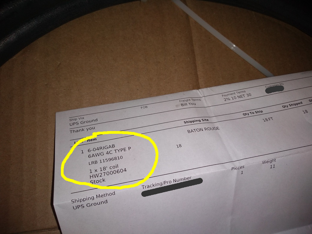
Figure 31: I ordered armored cable but received this unarmored cable (shipping invoice product number circled).
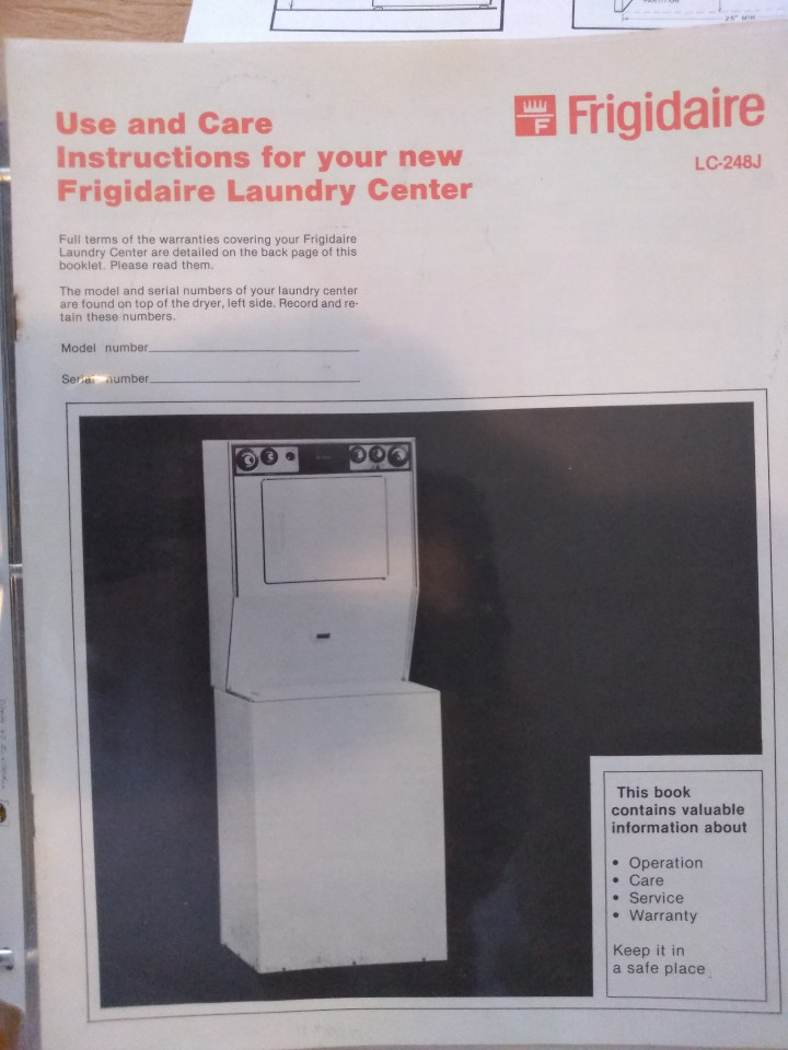
Figure 34: Wiring instructions. I have removed the bonding jumper between GND and NEUT to make compliant with modern code.
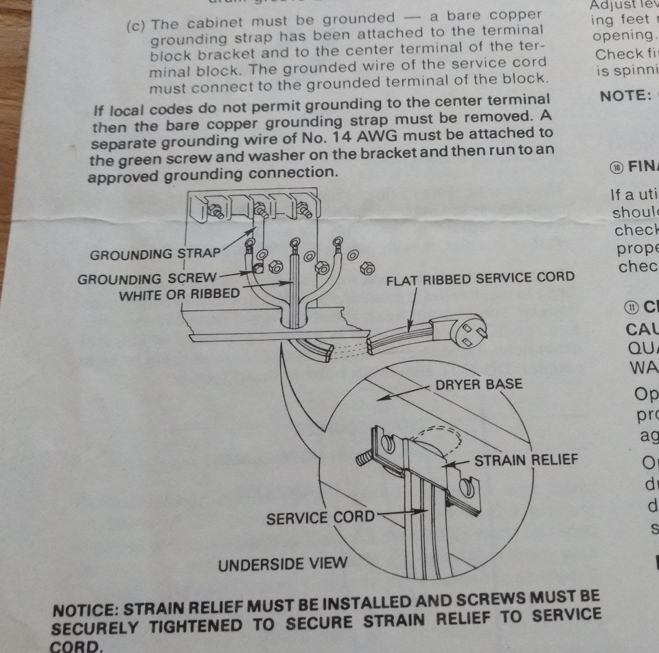
Figure 35: Washer Dryer schematic. NEUT/GND bonding jumper has been removed and a separate chassis GND 10 AWG wire run to power panel to separate NEUT & GND per modern code. Originally, coach had NEUT and GND bonding throughout.
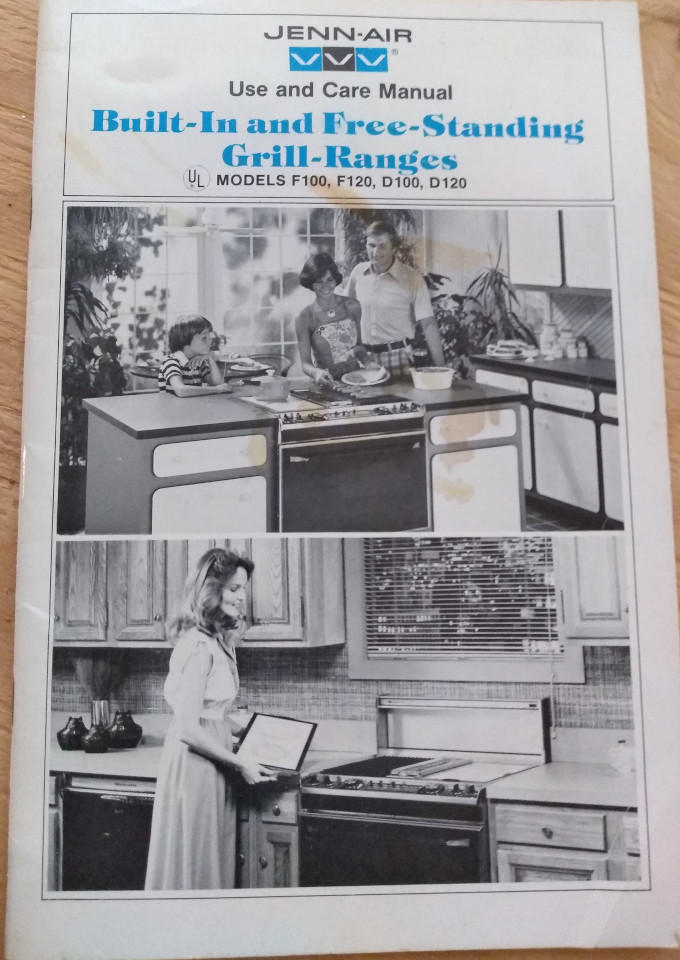
Figure 36: 240v JennAir Range. NEUT and GND have been separated and a new GND wire run to the power panel. A NEUT is necessary because of electric clock (120v presumably).